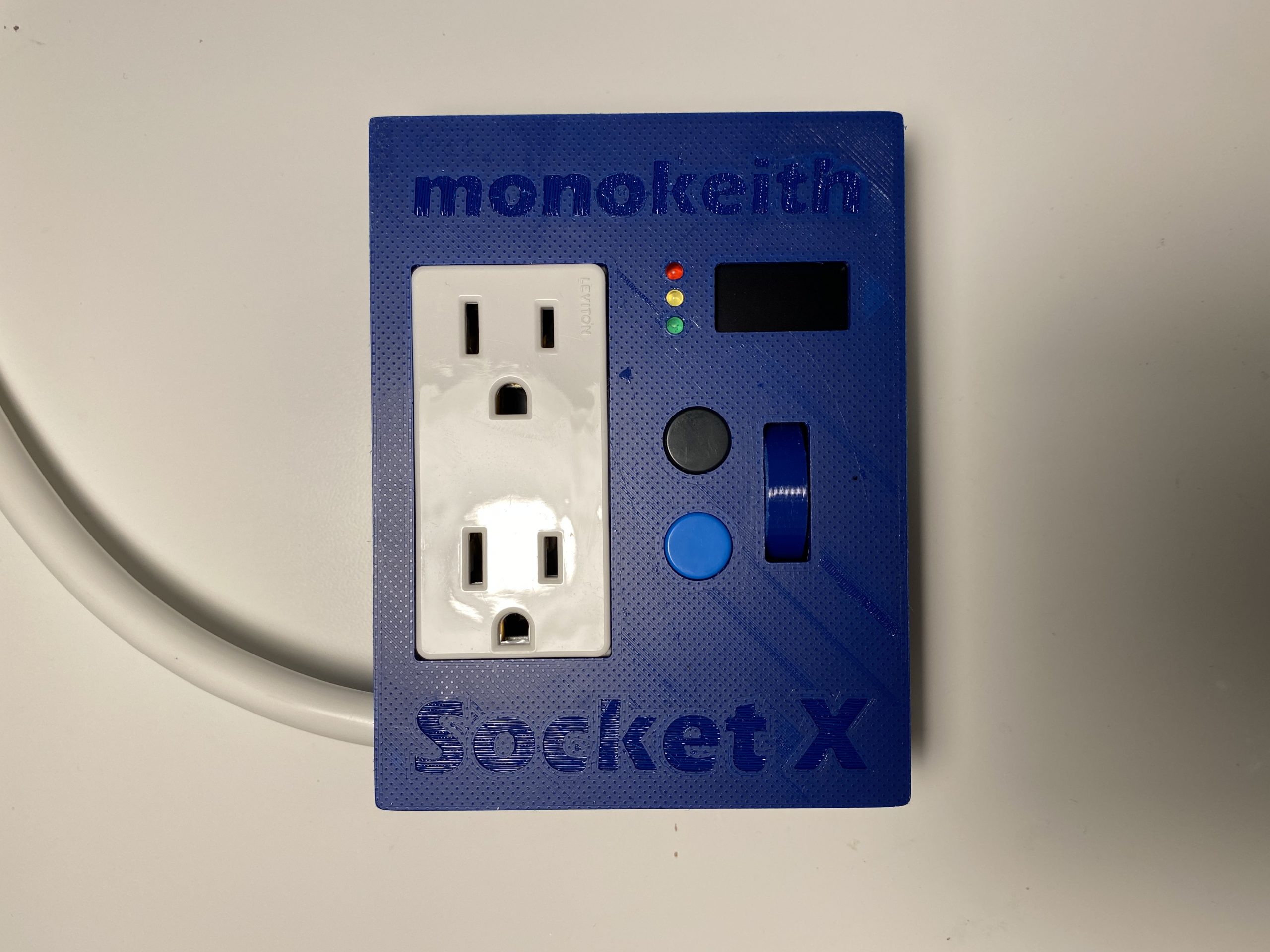
Code & TestButtons, Display, EncoderSoldered on board3D printed case3D printed caseSolder input and output wires to 5V power supplyInstall power supply in caseInstall socket and circuit board3D printed scroll wheelScroll wheelSolder everything to a RaspberryPi PicoTest bootHot glue in placeInstall backplateCompleteFinish
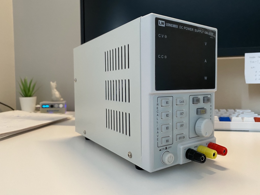
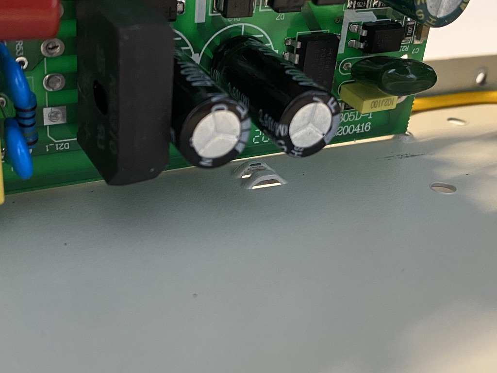
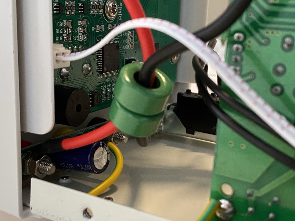
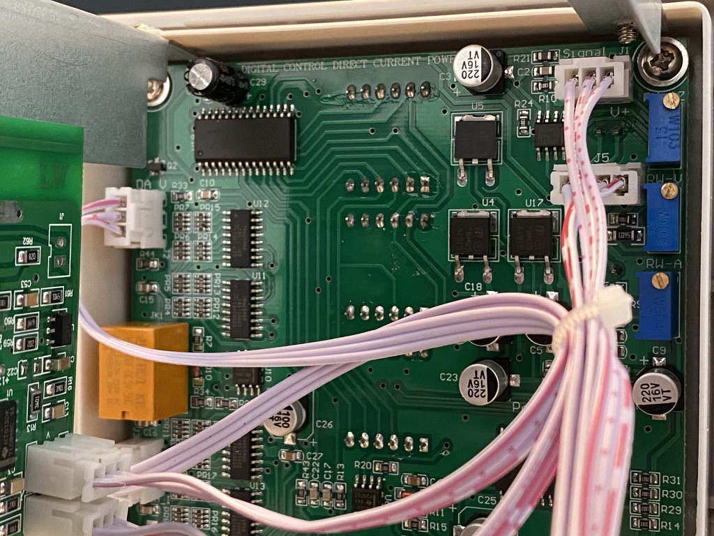
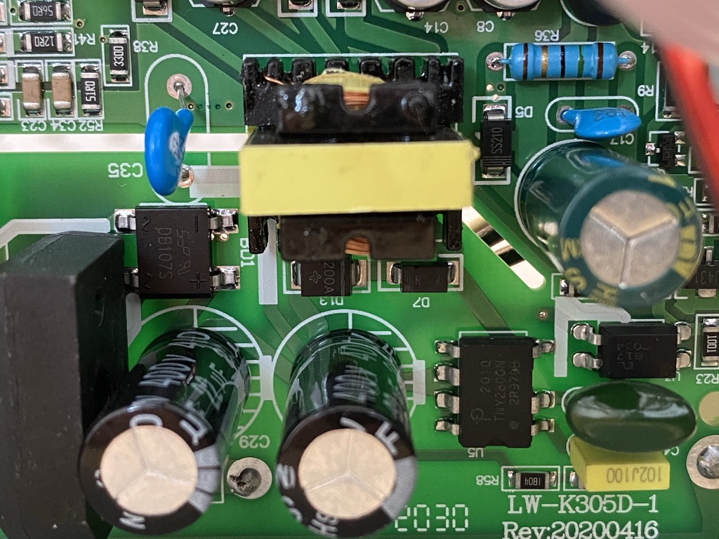
The input capacitors doesn’t have any kind of discharge mechanism. Even if the power supply is unplugged, these capacitor still holds near 300V DC. Proceed with cautious.
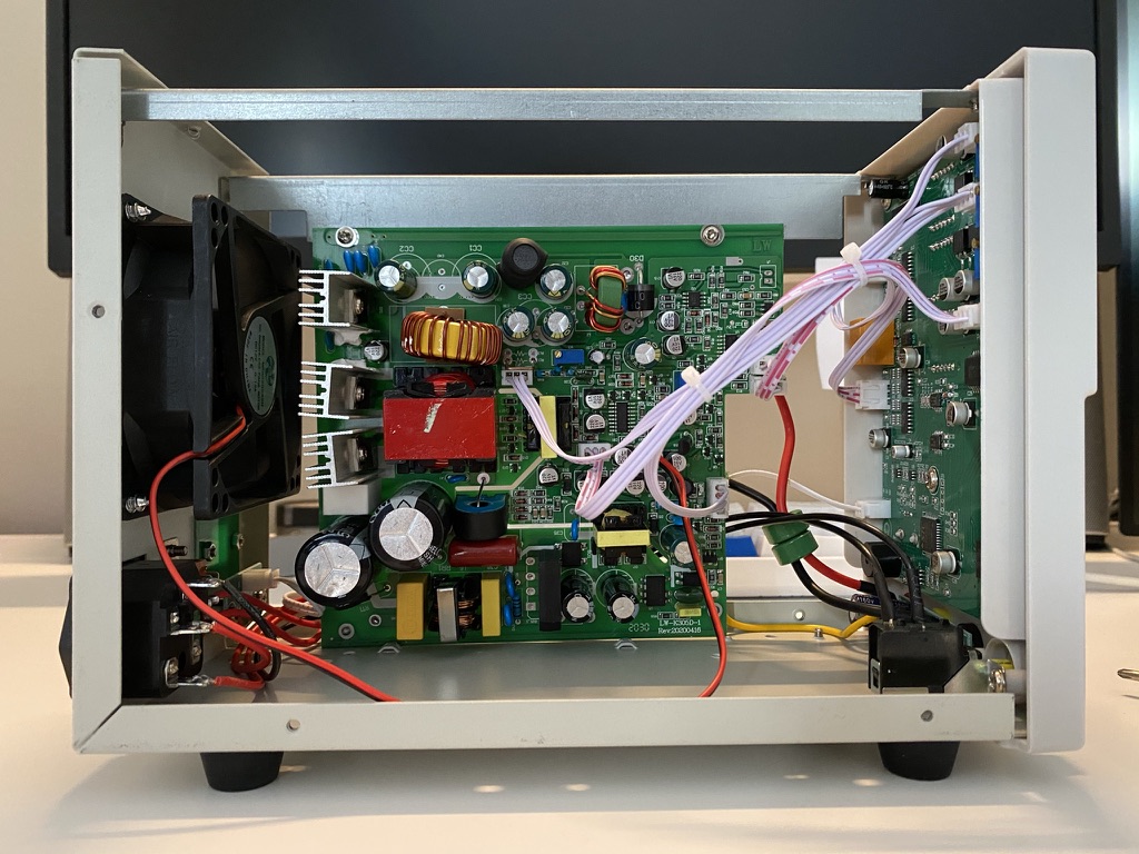
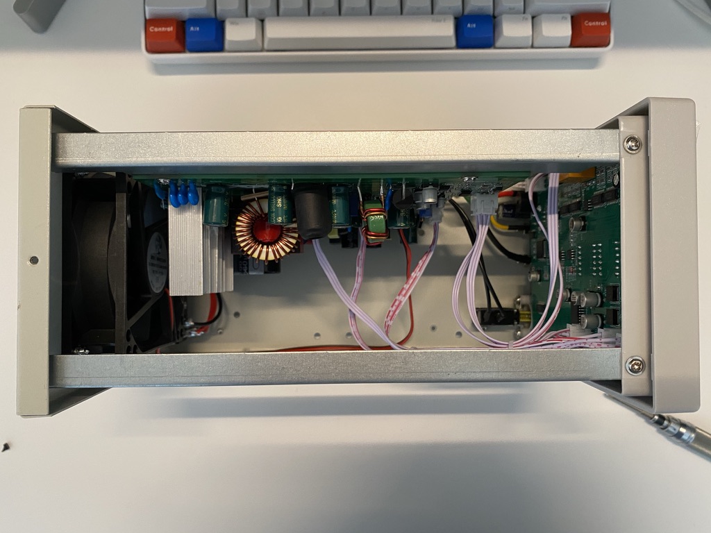
Interior
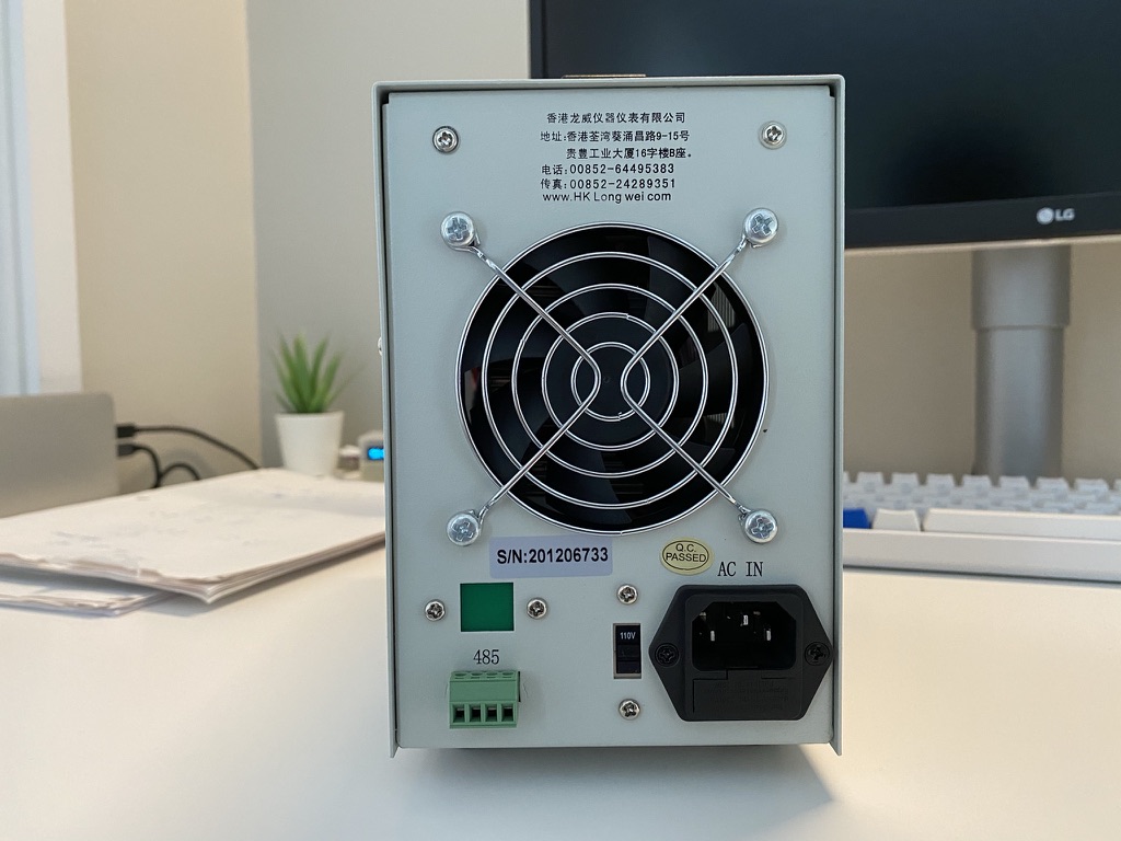
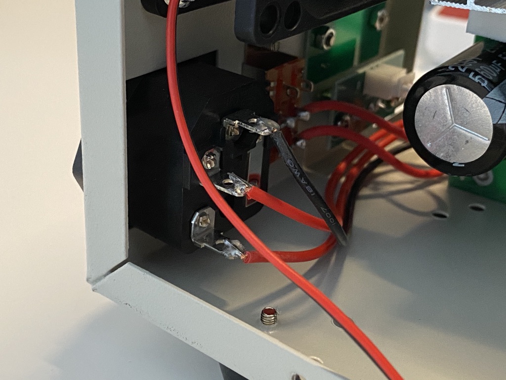
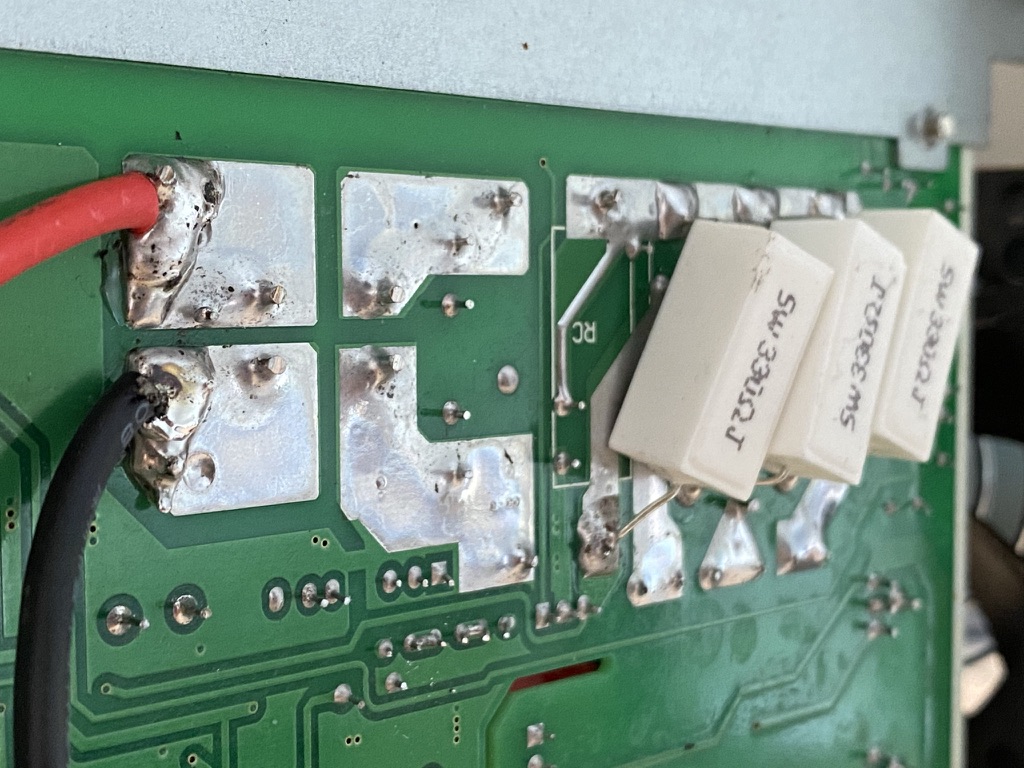
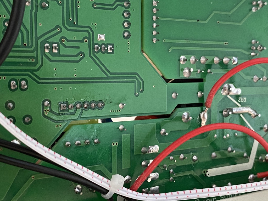
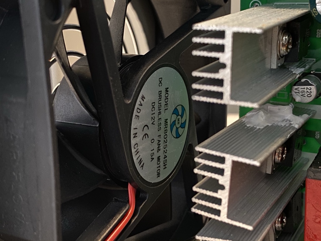
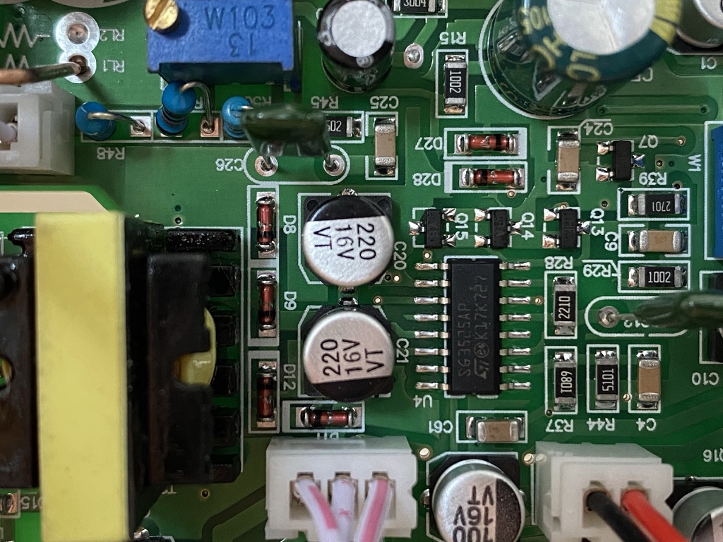
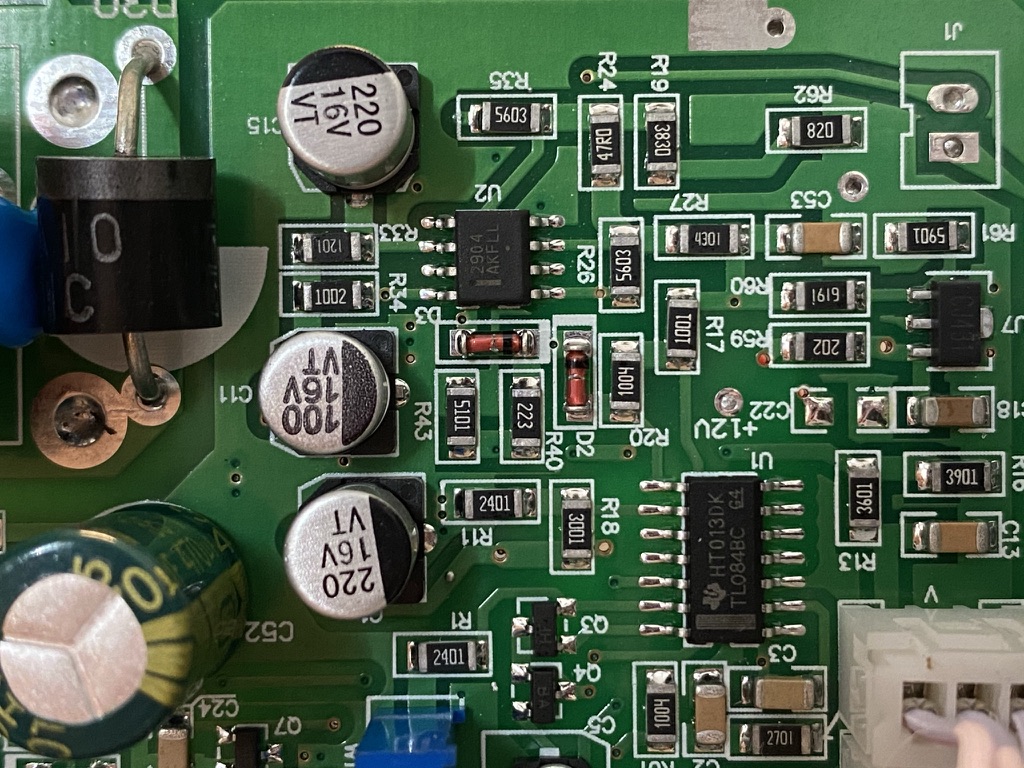
PCB FrontPCB RearTopPower input socketPCB should have sit in between the notch, somehow it falled out. DC output wiresDisplay PCB: adjustableDC output wire solderingInsulation gap & red wires connects to input (110V/220V) voltage switchCooling fan: 12V
Connect [Battery] and [ACC] cable from hardwire kit to fuse tap
Install fuse to fuse tap, I put 3A for [ACC] and 5A for [Battery]
I set cut off voltage to 12.2V, which is around 50% for normal 12V lead batteries. (More info about lead battery here)
Installation
Open fuse box in the cabin
The hardwire kit requires 2 cables, [Battery] provides constant power, and [ACC] is only for signalling the dash cam to go into parking mode. In this case, I choose [ILLUMI] for [Battery], and [12V SOCKET] for [ACC]. (there are more than 1 possible configuration here, you may use a multimeter to make sure you’re connecting to the correct one)
Tear down A pillar, route rear camera cable through the back of the air bag
My model is equipped with Subaru Eyesight, there’s a gap in the middle for powering Subaru HomeLink, however I didn’t get this option (too expensive 🙈), so I can use it for routing wires.
The rear camera cable integrated nicely with the top trim 🎉
Plastic trim on the left of the fuse box, remove it with plastic tool (to prevent scratches)
Plastic trim removed
Unplug fuse in slot [12V Socket] and [ILLUMI], install them to fuse tap accordingly
Fuse tap installed
Route ground [GND] cable through the gap
Attach it to the frame by the screw
Route the power cable the same way as the rear camera cable through the top trim, insert it in A pillar which goes to the fuse box
These 2 wires must stay behind the air bag (between the air bag and the frame), otherwise your air bag may not be able to protect you when it needs to.
Now both cable for front dash cam is done
The power cable can be route through the hole in the frame
Tighten all excessive cables
Close the fuse box
Install front dash cam, pull rear camera cable from the other end, make sure the cable in front is just long enough to be able to plug in
Pass the rear camera cable through B pillar
Stick rear camera in place
By installing it this way, instead of sticking it on the glass, the camera won’t block a lot of view, also maintaining a clean look
(if you have to stick it on the glass, make sure to avoid heating wires, those wires are very fragile and might break when you need to remove the camera in the future)
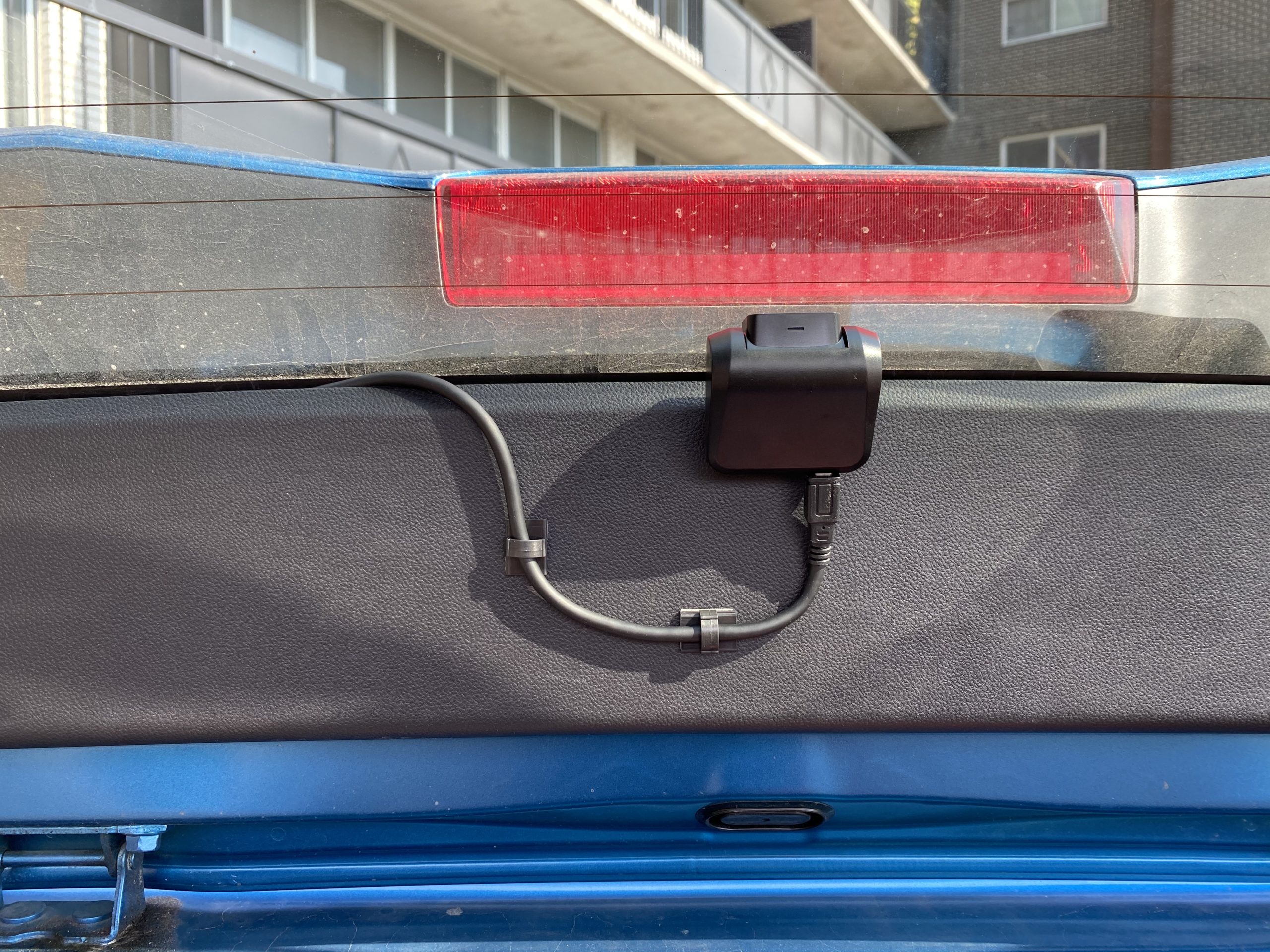
Since this cable is very long, I decided to integrate it into the rubber tube along with the break light cable located on the top left corner
Unscrew the Philips head screw on left plastic panel
Now we get a small gap between the frame and the panel, which is just larger enough to route the cable through (no need to take the whole panel off)
This thick black cable/pipe is either for washer fluid or break light (not important), it run through the hole on top, and goes into the rubber tube that connects the hatch with the frame
Take apart the rubber pipe from the frame
Run our rear camera cable through the hole
Reinstall the rear back plastic panel (BTW you can hide the cable in the panel just before the gap is closed)
I route the cable below the triangular window, inside the plastic trim, that it looks exactly as original
Tear apart the plastic trim on top of the hatch (no tool needed)
Run the camera cable through the rubber tube (it was very tight, I spent around 5 minutes to slowly forcing it through)
An easier/ faster way is to use a fishing wire to pull it through, but buying one probably takes more than 5 minutes anyway
Pull the wire through the rubber tube, reattach the tube to the frame
Run the wire through any hole in the hatch
Re-attach the rubber tube to the hatch, then hide excessive part of the wire in the hatch
Reinstall the plastic trim
I added 2 clips so the the wire won’t move anymore
Done
Credits
The routing process was inspired by the video below (that I found on Youtube). Luckily, Impreza shares most of the design with Forester, especially the fuse box part. It took me around 2 hours to do everything including taking pictures.
OpenCore 0.6.0 had been released yesterday on Github, as well as a lot of other kexts.
The EFI file above included update for following kexts:
OpenCorePkg 0.6.0
Lilu 1.4.6
WhateverGreen 1.4.1
VirtualSMC 1.1.5
AppleALC 1.5.1
AirportBrcmFixup 2.0.8
This configuration had been tested for BigSur Public Beta 1, Developer Beta 3, as well as Catalina 10.15.6, please refer to OpenCore 0.5.9 post for specific BIOS and hardware configuration.
Known Issue:
DRM not working for Safari in BigSur, but FireFox is fine
Since Clover BootLoader is reaching its end of life, it’s time to switch to OpenCore BootLoader.
This is the last version of Clover I used on my desktop.
Specs
Motherboard: ASUS Prime Z390-A (BIOS Release Date: 2020/05/04 Version: 1502)
CPU: Intel Core i9 9900K
Memory: 2 * Corsair Vengeance LPX 16GB 3200Mhz
GPU: MSI Radeon RX 5700 XT Gaming X
SSD: Western Digital WD Black SN750 500GB
Wireless: Fenvi FV T919
BIOS Configuration
Ai Tweaker
Ai Overclock Tuner: XMP II
ASUS MultiCore Enhancement: Enabled – Remove All limits
DRAM Frequency: DDR4-2933Mhz
I have stability issues (display halt) if I run at memory’s default 3200Mhz
This is probably due to BCLK/DRAM multiplier, the real iMac 19,1 runs its memory at 2666Mhz , which means multiplier was set to 100:133. I found a comment saying “some platforms do not like high memory multipliers”, but I need to test it out.
SATA Controller(s): Disabled [I don’t use any SATA Drives]
Onboard Devices Configuration
PCIEX16_3 Bandwidth: X4 Mode [I have my SSD installed on that port]
Serial Port Configuration
Serial Port: OFF
USB Configuration
Legacy USB Support: Disabled
XHCI Hand-off: Enabled
Boot
Boot Configuration
Fast Boot: Disabled
Secure Boot
OS Type: Windows UEFI Mode
USB Ports
By using Hackintool, I selected 15 USB ports that I needed and blocked the rest of them. You probably need different configuration to make your setup works (either reconfigurate or avoid using ports that are blocked).
Green: Ports that works
Red: Ports that won’t work
Some devices that are not being supported on macOS will cause problems. For example, my Oculus Rift S (which doesn’t have software support under macOS) causes instant wakeup, the solution is to plug it into one of the ports that are blocked, so it won’t even show up under IORegistryExplorer.
The configuration was set to use discrete graphics, so the onboards video output won’t work.
I used the bottom connector from USB1112 for Bluetooth connection integraded to my wireless card (Fenvi T919). USB_E12 and USB_E34 was connected internally via a USB 2.0 Hub, not only makes the USB device tree looks messy, but also brings some chances of not being able to discover Bluetooth hardware if the Bluetooth USB is connected to one of them.
Although I blocked USB_E12 and USB_E34 in the configuration, they are still useful for connecting devices that works on Windows but not needed for macOS, like AIO water pump and RGB controller.
My case doesn’t have a front USB-C connector, so the U31G1_C5 is blocked.
EFI File !!! Fill in SMBIOS informations before use.